When I was introduced to Makey Makey at a workshop hosted by a friend of mine last year, I saw great potential to spice up my English lessons. Then I saw the price tag.
After a little research, I found this great instructable about how to make your own Makey Makey using an Arduino Leonardo. Besides the cost of the Leo, you can make a device that emulates most of the Makey Makey’s functions for a couple of bucks!
I made one and it worked OK, but I found a way to make it better. Check out the materials and wiring diagram sections below to find out what I changed (OK, that sounds clickbaity; I just used different resistors).
Note that I said my “Fakey Fakey” can do most of what the Makey Makey can do. This guide will not help you make the gamepad type board in the signature Makey Makey style. You will be able to use it for the famous Banana Piano though!
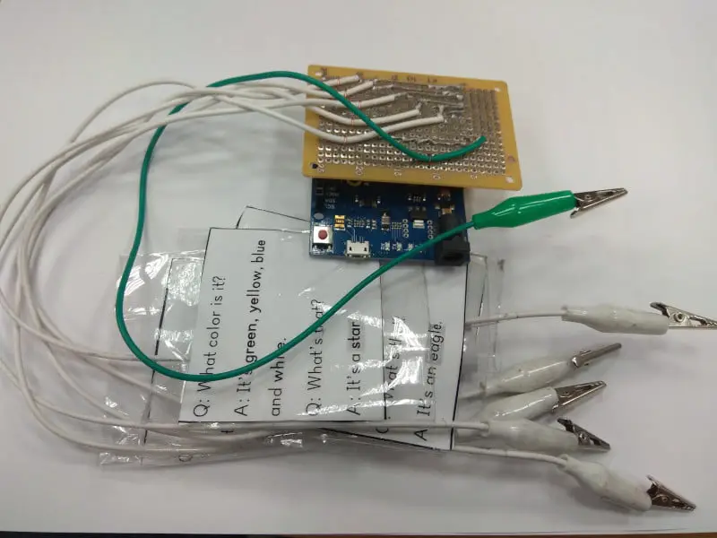
Table of Contents
Materials Needed
- 1 Arduino Leonardo
- 1 Micro USB cable
- 6 22MOhm 1/4 watt resistors
- 1 Blank prototyping board at least 21 holes x 12 holes
- 12 male header pins
- 7 alligator clip jumper wires
- Some scrap solid wire
Notes for Materials:
Board
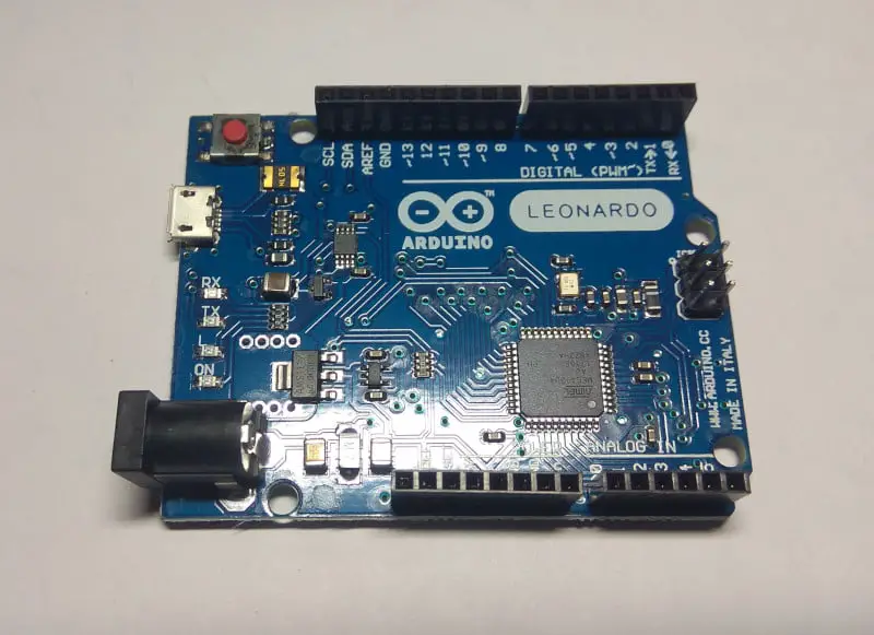
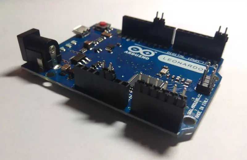
If you read my guide for making a recording sign for OBS, you might remember why we need to use a Leonardo instead of a regular Uno. The Leo is based on the ATmega32u4 chip which has a USB controller, thus letting it act as a keyboard. In fact, this is the same chip that the Makey Makey uses.
Resistors
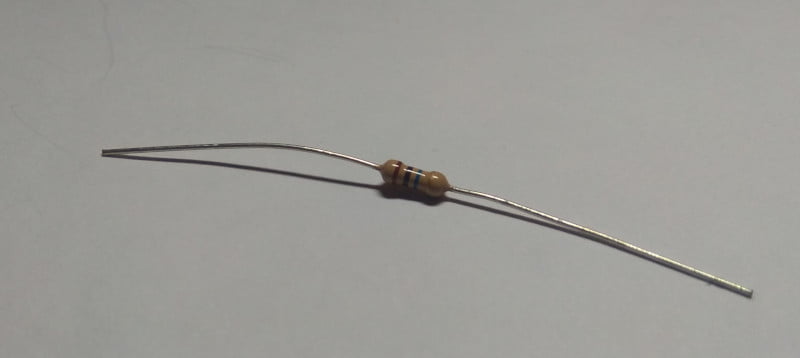
In the guide that I mentioned above, they use 1 megaohm resistors. I followed that guide for my first Fakey Fakey. It worked OK when directly touching the leads But when grasped the ground wired in my left hand and touched a graphite drawing that was attached to a lead, it only worked sporadically. After some research, I bumped the resistors up to 10 megaohms, and everything worked fine. I’ll explain why in the wiring diagram section.
Prototyping board
Like this but without the components
I don’t know what to call these really. On Amazon, I see them sold as ‘blank PCB boards’ (printed circuit board boards?). But there is nothing printed on them. You could use a breadboard, but as I was planning on using my Fakey in a classroom setting with a bunch of rowdy third-graders, I needed something more rugged.
Header pins
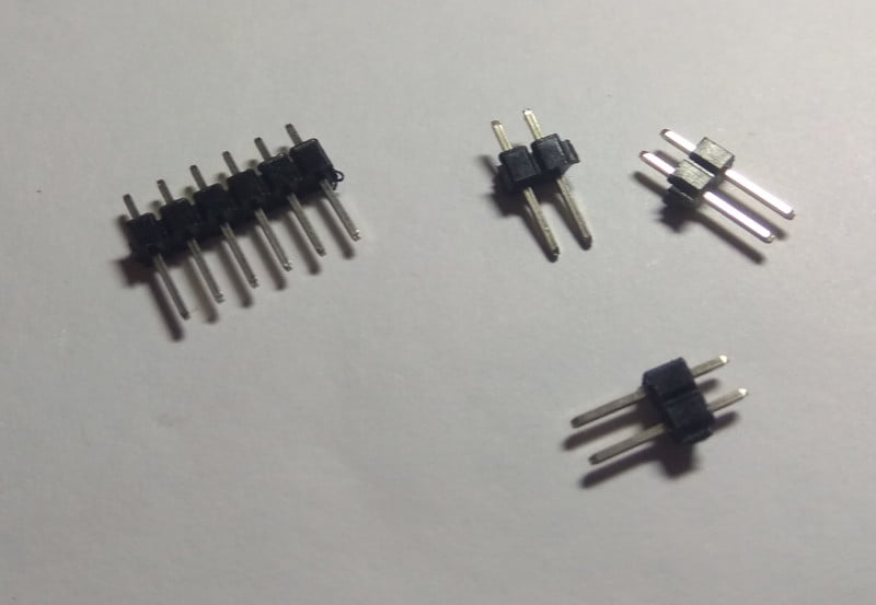
I had a bunch of these lying around because the Wemos boards that I love always come with a big selection of header pins. If you want the prototyping board to attach to the Arduino like a shield, you have to use male pins.
Jumper wires
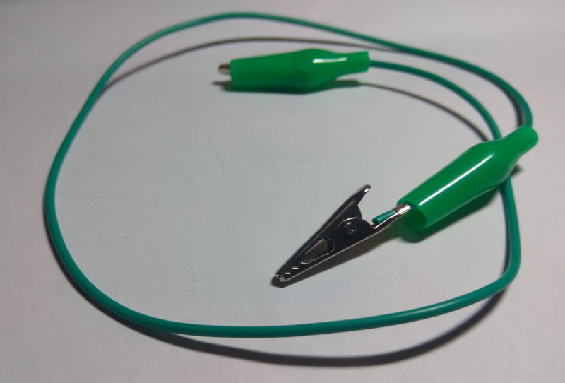
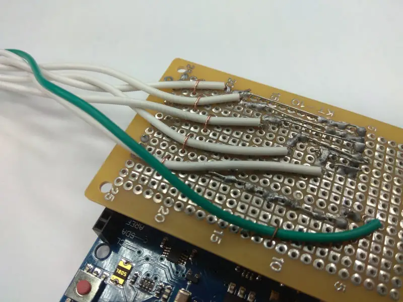
I’m not sure what gauge the wires I used are, but they are not much thicker than the jumper wires that come with Arduino kits. If you can find some with alligator clips on one end, and no connector on the other that would be ideal. Again, because of rambunctious kids, I opted to solder mine to the board.
To keep things simple, I chose one color for the active leads, and green for the ground lead. Using multiple colors for the active leads might have confused the students.
Scrap wire: Even with the lead wires soldered to the board, I was afraid that the little gremlins would rip the wires off the board. So I used some copper wire to secure everything to the board and take the stress off the solder points. Anything small enough to fit through the prototyping board holes will work.
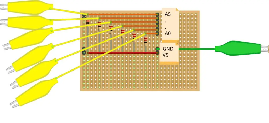
Wiring Diagram
The wiring for this project is simple enough. The finished product will be six leads that when connected to ground will create a voltage divider.
Chabuduo
So, as long as a lead is not connected to ground, there is no voltage division, and a relatively high signal is sent to the corresponding pin on the Leo. If you complete the circuit with ground, the voltage going to the pin will drop, and the Leo will see it as a low signal.
Sparkfun has a great explanation of voltage dividers here. The tldr; version is that the two resistors of a voltage divider should have a difference in resistance by order of magnitudes.
You may have noticed that each circuit in the wiring diagram above only has one resistor. That is because your body acts as the second resistor when you hold the ground wire in one hand, and the lead wire in the other.
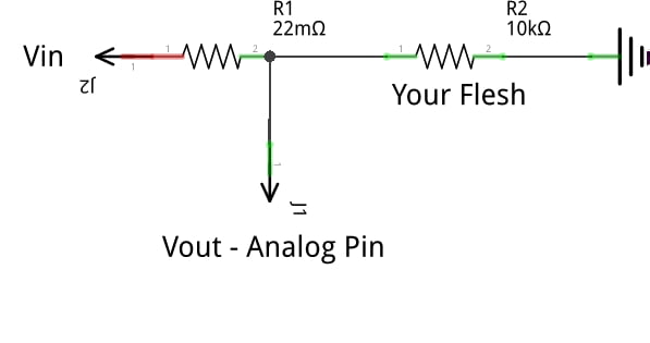
The most natural of voltage dividers
The resistance offered by the human body ranges from 10,000 ohms to 100,000 ohms depending on various factors. Using a 1 megaohm resistor should be perfect then, right? Even in bad conditions, it is still a magnitude larger.
But the fun of Makey Makey is using random objects as buttons! However, once you add the resistance of the object to the resistance of your body, there is not enough difference in the two resistance values for the voltage divider to reduce the output to low.
In writing this guide, I tested the resistance of one of the cards that I used in class. You can see the results below. This letter was colored in with a soft, 6B art pencil. I found that the resistance from the lower end of the C (marked 0) to the middle of the C was already 160 kiloohms!

And that’s why Makey Makey uses 22 megaohm resistors, and you should too. I used 10 megaohm resistors and my Fakey Fakeys only worked about ninety percent of the time.
Putting it together
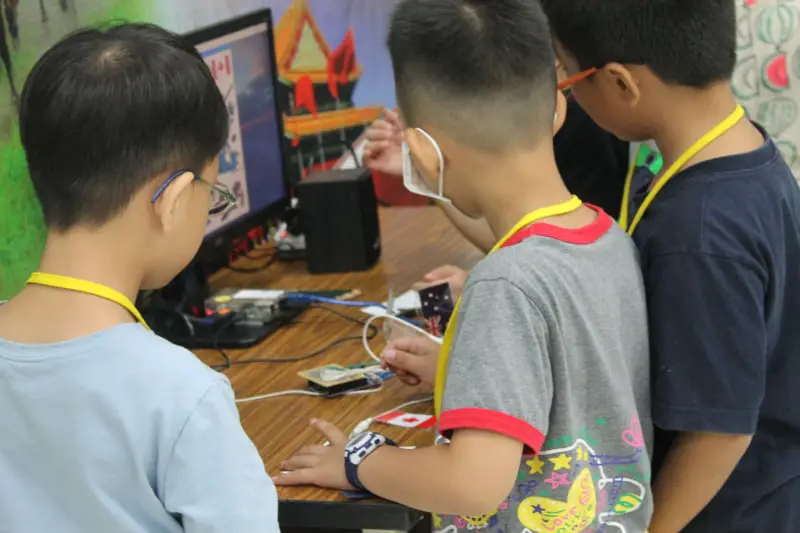
Did I mention that I used these Fakey Fakeys with classes of around 27 first through third graders? While I strongly encourage that you test your Fakey Fakey using a breadboard first, if I hadn’t made a more sturdy device, my class would have been over before it started.
Before we get to any pictures, I just want to say, I know my soldering skills need some work! If you have any tips, leave them in the comments.
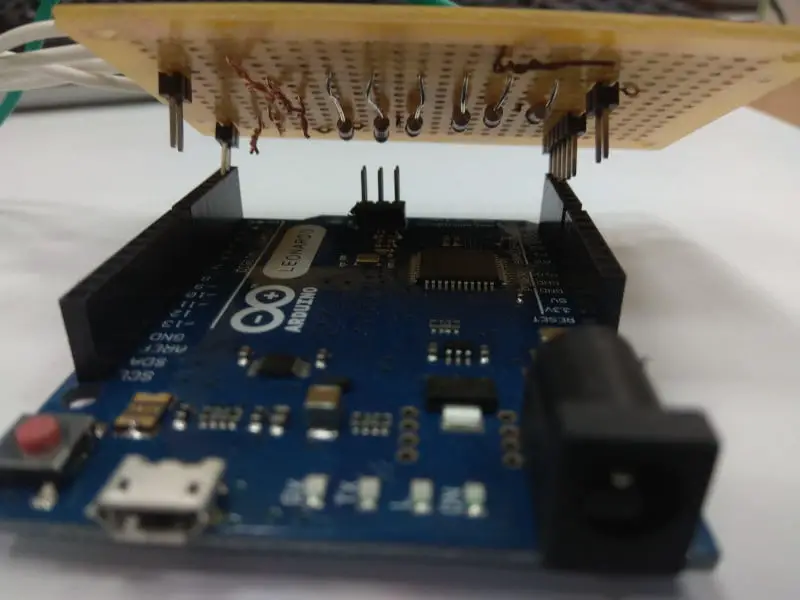
First, the headers should be added to the prototype board so you have a reference point when adding the rest of the components. Insert the long side of six of the header pins in the A0 – A5 female pins. Also, insert a ground and 5V on the same side of the board as the analog pins.
On the opposite side of the board, insert two sets of two pins in any of the header pins on the Arduino. These pins are just to keep the Fakey Fakey in place, so you can use any pins you wish.
After you’ve inserted all the pins, place the prototyping board on top of the Leo so that the short end of the new header pins go through the holes on the blank board. If your blank board is wider than the Arduino, let it hang over on the analog pin side. Also, if you are not using a double-sided board, make sure you have the solderable side facing up.
After you solder the pins to the prototyping board, remove it from the Leonardo. It’s time to start adding resistors.
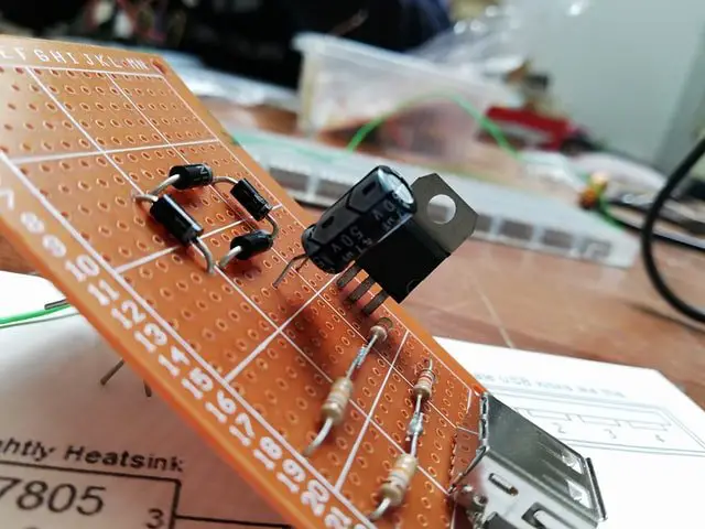
How you lay out your components is up to you. The goal is to connect each of the analog pins to the 5V pin via a resistor. Along with the ground pin, each of the analog pins is also connected to a jumper wire.

After you have finished soldering everything, secure the jumper wires to the board with some wire. This helps keep those overexcited students from ripping the wires off your Fakey Fakey.
Your new Fakey Fakey can now be attached to the Leonardo!
Fakey code
The code from Simone Ferrecchia’s instructable can be downloaded here. The only change I made was to assign A – F to the pins instead of the generic Makey Makey keymap. I will briefly highlight the key components below.
We’ll only need to import a few libraries. Keyboard will let the Leo send keypresses to the attached PC. MovingAvg smooths out the signal being received by the analog pins.
#include <Keyboard.h>
#include <movingAvg.h>
Later, we’ll be using the analogRead function which reads the voltage on the analog pins and converts it to a value between 0 and 1023. The declarations below set the high and low threshold for the value read.
const int PressedMaxThreshold = 200;
const int ReleasedMinThreshold = 300;
Also, we will need to know how many pins we are using later.
const byte PinCount = 6;These two arrays map keys to the analog pins. Here, the original keymap, d-s-w-a-z-e to my own, A-B-C-D-E.
const byte InputPins[PinCount] = {A0, A1, A2, A3, A4, A5};
const char KeyCodes[PinCount] = {'A', 'B', 'C', 'D', 'E', 'F'};
The next bit is really interesting. Arduino has a data object aptly named STRUCT. The following will define a data structure called TouchInput that holds the pin number, key letter, average input value, and state of each pin.
struct TouchInput
{
  byte analogPin;
  char keycode;
  movingAvg filter = movingAvg(20);
  boolean wasPressed = false;
};
Passing the integer 20 to movingAvg means that it will use the last 20 data points to create an average. Next, we create a TouchInput object called Pins.
TouchInput Pins[PinCount];In the setup loop, besides starting serial data transmission, all we need to do is use the two arrays we created earlier to populate the Pins structure with some data. We also initiate the moving average for each pin.
for (int i = 0; i < PinCount; i++)
  {
    Pins[i].analogPin = InputPins[i];
    Pins[i].keycode = KeyCodes[i];
    Pins[i].filter.begin();
  }
Because of the beautiful way everything is stored in the Pins object, the main loop is very straightforward. If you haven’t already, you can download it with the link at the top of this section.
We simply loop through Pins and check to see if it’s receiving a value below the low threshold. If it is, we know the voltage divider we created earlier is in action, meaning someone has completed the circuit. A keypress is then sent.
You can upload the sketch to your Leo with Atom or VS Code with the PlatformIO plugin. Of course, you could use the official Arduino IDE, but I’d wait until Arduino Pro IDE has been released.
My simple English lesson using my Fakey Fakeys is coming soon!
You might also be interested in reading about creating a DIY remote control Arduino recording sign for OBS!